Programmer
Flash firmware to ESP32, STM32 and AVR — right from the terminal
The Programmer tab flashes firmware to four families of microcontrollers over the same serial port the rest of the app uses. It talks to the chip's built-in UART bootloader — so all you need is a USB-to-serial adapter, no external hardware programmer (JTAG/SWD). Pick a chip, pick a file, click Flash; you do not leave ComIO.Studio and you do not open esptool or STM32CubeProgrammer.
Which chips
Four families, each with its own backend:
- ESP32 (all variants) — through the
espflashcrate. - ESP8266 — through
espflashas well, on a separate code path. - STM32 — through the chip's UART bootloader (specification AN3155).
- AVR — through the STK500v1 protocol.
The list of supported chips comes with the app — pick one from the target list. Each chip carries its own flashing instructions (boot mode, pinout, what to connect) in the info panel.
The Flash tab
The Programmer tab sits on the right side of the window. It has three sections that are always visible: the chip and file setup at the top, the actions in the middle, and a terminal of its own at the bottom — the programmer writes its progress there, separate from the main terminal.
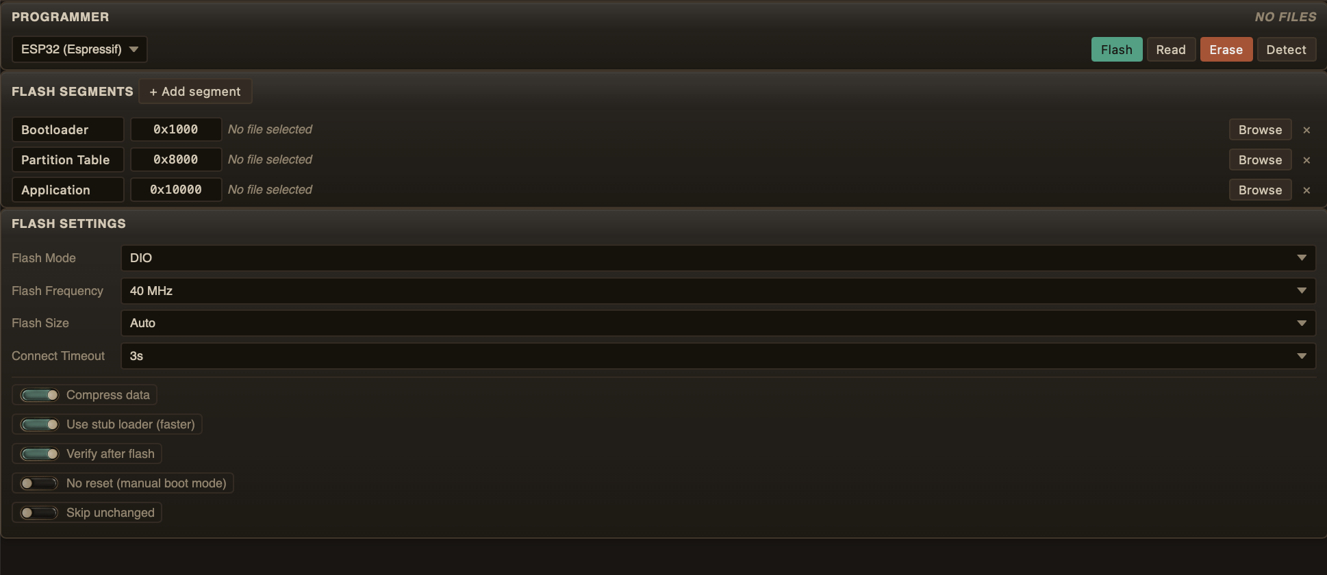
The Programmer tab — chip and segments at the top, actions in the middle, the programmer's own terminal at the bottom
Segments — where each file goes
A chip's flash is addressed in segments. Each segment has an address and a file to write there. The app fills in the standard layout for each family when you pick a chip:
- ESP32: Bootloader @
0x1000, Partition Table @0x8000, Application @0x10000. - ESP8266: Bootloader @
0x00000, Firmware @0x01000, Init Data @0xFC000, plus two blank segments for RF calibration (0x7E000) and system parameters (0xFE000). - STM32: Firmware @
0x08000000. - AVR: Firmware @
0x0.
Pick a file for each segment you actually want to write — leave the others empty. Addresses are editable, so a non-standard layout is just a typed number. For ESP32/ESP8266 you can add more segments with a + button. The ⚙ button next to the family opens target-specific settings: flash mode and frequency for ESP, page size for AVR, full erase and the protection toggles for STM32.
Actions
- Detect — read the chip's signature and show its name, flash size and features (MAC for ESP).
- Flash — write the files you picked to the segments you picked. Runs in the background with a progress bar, so the app stays usable.
- Erase — wipe the whole flash.
- Read — read the flash back to a file on your disk.
- Info — read chip info (signature, flash size).
- Write unprotect / Readout unprotect — remove the chip's write and readout protections (STM32). Readout unprotect mass-erases the chip.
Progress and the programmer's terminal
Flashing is asynchronous — the bar fills and messages scroll in the
programmer's terminal at the bottom of the tab. The main terminal is not touched; the
programmer talks to you in its own window, with its own log lines (LOG_PROG,
OK_PROG, WARN_PROG, ERR_PROG — see the Terminal
chapter). When the flash is done, the bar settles; on error, the message tells you what went
wrong.
Boot mode
Most boards need to be put into a boot mode before they will accept a flash. The info panel for each chip says how:
- ESP32 / ESP8266 — mostly automatic: ComIO.Studio toggles RTS and DTR for you. On a board without an auto-reset circuit, hold GPIO0 LOW and reset.
- STM32 — set BOOT0 HIGH, then reset.
- AVR — reset the board; the bootloader activates on its own.
Example: ESP8266 AT firmware (1 MB flash)
Segment 1: Bootloader    @ 0x00000  → boot_v1.7.bin
Segment 2: Firmware      @ 0x01000  → user1.1024.new.2.bin
Segment 3: Init Data     @ 0xFC000  → esp_init_data_default.bin
Segment 4: Blank (RF)    @ 0x7E000  → blank.bin
Segment 5: Blank (sys)   @ 0xFE000  → blank.bin