 User Guide
Click on any topic to expand step-by-step instructions
🎬 Video Tutorials
Getting Started — Serial Connection, Macros & Triggers
Additional tutorials are being prepared for Lua scripting, firmware flashing, and the AI assistant.
 Connecting to a Serial Device
Connect to any serial (UART / RS-232) device through a USB-to-serial adapter or a built-in USB serial interface (like on Arduino or ESP32 DevKit boards).

Connection panel — port selection, baud rate, control lines
Step by step
- Plug in your device — USB-to-serial adapter, Arduino, ESP32, or any serial device. ComIO.Studio will auto-detect the new port via USB hotplug — it appears in the dropdown automatically.
- Select the port from the Port dropdown (e.g.,
/dev/ttyUSB0on Linux,COM3on Windows). You can also click the ⟳ (refresh) button to manually refresh the list. - Set Baud Rate — choose from the dropdown. Must match your device. Most common:
9600or115200. - Optionally adjust other settings:
- Data bits: 5, 6, 7, or 8 (default)
- Parity: None (default), Odd, or Even
- Stop bits: 1 (default) or 2
- Flow control: No FC (default), XON/XOFF, or RTS/CTS
- Click "Connect".
- The LED indicator turns green, status shows "On", and the status bar displays your configuration (e.g.,
115200 8N1 No FC). - Incoming data now appears in the terminal window.
Changing settings while connected
You can change baud rate, data bits, parity, stop bits, and flow control while connected — changes are applied instantly without disconnecting.
Control lines
Two toggle switches let you manually set output lines:
- RTS (Request To Send) — toggle on/off
- DTR (Data Terminal Ready) — toggle on/off
Four read-only indicators show the current state of input lines:
- DSR (Data Set Ready), CTS (Clear To Send), DCD (Data Carrier Detect), RI (Ring Indicator)
 Terminal Display & Data Buffer
The main terminal window shows all incoming (RX) and outgoing (TX) data with color coding — green for RX, blue for TX.
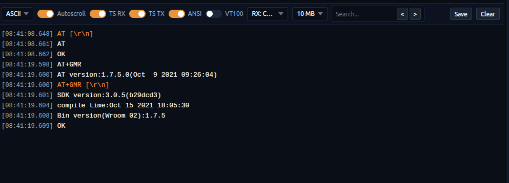
Terminal with toolbar — encoding, timestamps, search, ANSI/VT100
Toolbar controls
- Encoding — display format:
- ASCII (default) — text with line assembly
- HEX — raw bytes in hexadecimal
- ASCII + HEX — both together
- Autoscroll — when ON (default), terminal auto-scrolls to the latest data
- TS RX / TS TX — toggle timestamps for received / transmitted data (both ON by default)
- ANSI — parse ANSI escape codes for colored output (ON by default)
- VT100 — full VT100 terminal emulation with cursor positioning and screen control (OFF by default)
- RX line ending — how to split incoming data into lines: Raw, LF, CR, or CRLF (default)
- Buffer limit — maximum memory: 5 MB, 10 MB (default), 15 MB, or 20 MB
- 🎨 Terminal colors — opens a dialog where you can customize output colors:
- TX — sent data
- RX — received data
- Info — system / programmer messages
- Timestamp — time prefix
Search
Type in the Search field to highlight matching lines. Use < and > buttons to jump between matches. A counter (e.g., 3/15) shows your position.
Save & Clear
- "Save" — downloads terminal contents as a text file
- "Clear" — clears the terminal and resets RX/TX statistics
Right-click context menu
- Copy (Ctrl+C) — copy selected text
- Add to Send — paste selected text into the command input field
- Send — immediately send the selected text to the serial port
- Select All (Ctrl+A) — select all terminal content
- Clear Terminal — same as the Clear button
Statistics (sidebar)
- RX: bytes received
- TX: bytes sent
- Time: connection uptime
- Recon.: number of reconnections
 Sending Commands
The command bar at the bottom of the screen is where you type and send data to the connected device.
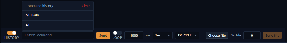
Command bar — input, send, loop, format, history, file send
Basic sending
- Type your command in the input field
- Choose format: Text (default) or Hex (e.g.,
FF 01 03 00) - Choose TX line ending: None, CR, LF (default), or CRLF — appended to every sent command
- Click "Send" or press Enter
Command history
Toggle "History" ON to see a dropdown with previously sent commands. You can also press ↑ / ↓ arrow keys to cycle through history. Click "Clear" in the dropdown header to erase all history.
Loop send
For repeated polling or keep-alive commands:
- Toggle "Loop" ON
- Set the interval in milliseconds (default: 1000 ms, range: 10–60000)
- Type your command and click "Send" — the command is sent repeatedly at the set interval
- The button changes to "Stop" (red) — click it to stop the loop
File send
Send the contents of a file through the serial port:
- Click "Choose file" and select a file
- Optionally set delay between chunks (0–1000 ms) for slow devices
- Click "Send file" — a progress bar shows the transfer status
 Using Macros (M1–M6)
Macros are one-click command shortcuts. You have 6 macro buttons (M1–M6) in the sidebar.

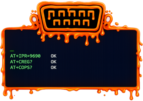
Macros section — quick-access buttons M1–M6
How to set up macros
- Click the "Edit" button in the Macros section — a modal window opens with all 6 macros
- For each macro, fill in:
- Name — the label shown on the button (e.g., "Reset", "Init")
- Data — the command to send (e.g.,
ATZorFF 01 03) - Mode — Text or Hex
- EOL — line ending: None, CR, LF, or CRLF
- Click "Save" to save all macros, or "Cancel" to discard changes
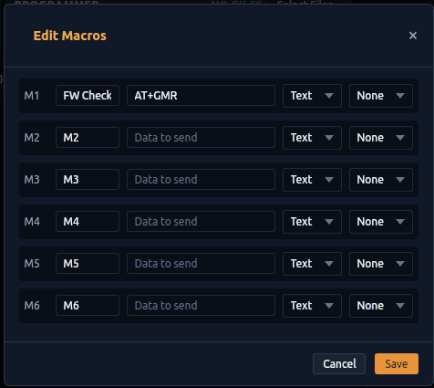
Edit Macros — name, data, format, and line ending for each macro
Using macros
Click any macro button (M1–M6) in the sidebar grid — the command is sent immediately. The button shows the custom name you set, or "M1"–"M6" if unnamed. Hovering shows a tooltip with the macro content.
Example: ESP8266 AT commands
M1: Name="AT"      Data="AT"        EOL=CRLF
M2: Name="Version" Data="AT+GMR"    EOL=CRLF
M3: Name="Reset"   Data="AT+RST"    EOL=CRLF
M4: Name="WiFi" Data="AT+CWLAP" EOL=CRLF Setting Up Triggers
Triggers watch incoming serial data and automatically send a response when a text pattern is detected.
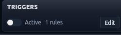
Triggers section — active toggle and rule count
How to create a trigger
- Click the "Edit" button in the Triggers section — a modal window opens
- Click "+ Add" to add a new trigger rule
- Fill in the fields:
- Pattern — the text to detect in incoming data (e.g.,
Password:) - → (arrow separator)
- Response — what to auto-send back (e.g.,
mypassword) - Mode — Text or Hex
- EOL — line ending: None, CR, LF, or CRLF
- Pattern — the text to detect in incoming data (e.g.,
- Click "Save"
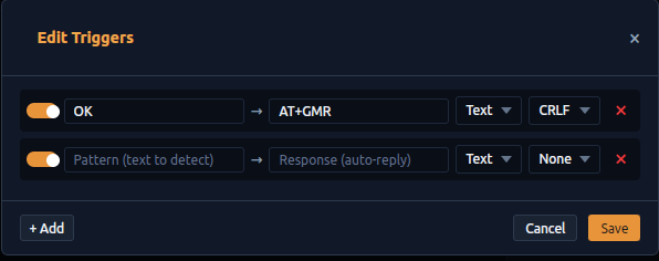
Edit Triggers — pattern, response, format, and per-rule toggle
Managing triggers
- Enable/Disable individual trigger — toggle switch next to each rule
- Remove a trigger — click ✕ on the right side of the rule
- "Active" toggle (in the sidebar) — enables or disables ALL triggers at once
- Rule count — shows how many rules are configured (e.g., "3 rules")
Example: Auto-login
Pattern:  "Password:"
Response: "mypassword"    EOL=CRLF

→ When the device sends "Password:", ComIO.Studio
  automatically replies with "mypassword\r\n".
Example: Keep-alive
Pattern:  "PING"
Response: "PONG"    EOL=LF

→ Device sends "PING" → auto-reply "PONG\n".
Lua Scripting
ComIO.Studio includes a Lua 5.4 scripting engine for automating complex serial communication workflows.
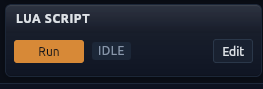
Lua Script section — Run/Stop, status indicator, Edit button
Script editor
- Click "Edit" in the Lua Script section — a modal editor opens with syntax highlighting
- Write your Lua code, or select an example from the "📚 Examples..." dropdown
- "Open" — load a
.luaor.txtfile from disk - "Save" / "Save As" — save your script to disk
- "Close" — close the editor (code is auto-saved in memory)
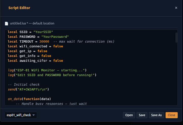
Script Editor — syntax highlighting, examples dropdown, file operations
Running scripts
- Make sure the serial port is connected (the Run button is disabled otherwise)
- Click "Run" — status changes to "Running"
- Script output appears in the terminal as
📜 [Script] ... - Click "Stop" to terminate a running script
Lua API Reference
-- ═══ Sending ═══

send("AT+GMR")              -- Send text (CRLF appended automatically)
send_hex("FF 01 02 03")     -- Send bytes from a hex string
send_raw("\x1b[2J")         -- Send raw bytes, NO line ending (ANSI/binary)

-- ═══ Receiving ═══

on_data(function(line)      -- Callback for each incoming line
    log("RX: " .. line)
end)
wait_for("OK", 5000)        -- Block until a line contains "OK" (timeout ms) → string|nil

-- ═══ Timing & timers ═══

sleep(1000)                 -- Pause ms (callbacks dispatch during sleep); delay() is an alias
millis()                    -- Milliseconds since the script started
set_timeout(2000, fn)       -- Run fn once after ms          → timer_id
set_interval(1000, fn)      -- Run fn every ms (minimum 10ms) → timer_id
clear_timer(id)             -- Cancel a timer

-- ═══ Utility ═══

emit("\x1b[32mhi\x1b[0m")   -- Write straight to the terminal (no serial port needed)
log("message")              -- Info message in the script log
log_warn("careful")         -- Warning message
serial_connected()          -- true if the serial port is connected
on_error(function(err) log_warn(err) end)  -- Serial error / disconnect callback
stop()                      -- Gracefully stop the script
Example: AT command test
log("Starting AT command test...")

send("AT")
local resp = wait_for("OK", 3000)

if resp then
    log("✅ AT responded OK")
else
    log_warn("❌ No response — check connection")
    return
end

send("AT+GMR")
resp = wait_for("OK", 3000)
log("Firmware: " .. (resp or "unknown"))
log("✅ Test complete!")
Example: Modbus RTU query
-- Read 10 holding registers from device at address 1.
-- The engine has no built-in CRC — here is a pure-Lua CRC16 (Modbus).
local function crc16_modbus(data)
    local crc = 0xFFFF
    for i = 1, #data do
        crc = crc ~ data:byte(i)
        for _ = 1, 8 do
            if (crc & 1) ~= 0 then crc = (crc >> 1) ~ 0xA001
            else crc = crc >> 1 end
        end
    end
    return crc
end

local addr, func = 0x01, 0x03
local start_reg, num_regs = 0x0000, 0x000A

local frame = string.char(addr, func,
    (start_reg >> 8) & 0xFF, start_reg & 0xFF,
    (num_regs >> 8) & 0xFF, num_regs & 0xFF)

local crc = crc16_modbus(frame)
frame = frame .. string.char(crc & 0xFF, (crc >> 8) & 0xFF)

-- Collect the binary reply as it arrives (on_data fires during sleep)
on_data(function(chunk)
    log("Response bytes: " .. #chunk)
end)

send_raw(frame)   -- send the frame as-is, no CRLF
sleep(500) -- give the device time to answer.lua files. Edit them in the built-in editor or any external text editor.
 Flashing Firmware (MCU Programmer)
Flash firmware directly to microcontrollers through the serial port (UART bootloader). This uses the chip's built-in UART bootloader — you only need a USB-to-serial connection, no external hardware programmers (JTAG/SWD) are needed.
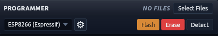
Programmer section — target selection, Flash/Read/Erase/Detect buttons
Supported chip families
- ESP32 (Espressif) — all ESP32 variants
- ESP8266 (Espressif) — ESP-01, NodeMCU, etc.
- STM32 (ST UART Bootloader) — chips with built-in UART bootloader
- AVR (Arduino STK500) — via serial bootloader protocol
Step by step
- Select your Target chip family from the dropdown.
- Make sure the correct serial port is selected in the Connection panel.
- Click "Select Files" — a popup shows firmware segments. Each segment has:
- Segment name (e.g., "Bootloader", "Firmware")
- Address — flash memory address (e.g.,
0x01000) - "Browse" — select a
.bin,.hex, or.elffile
- For ESP32/ESP8266 you can click "+ Add segment" to add more files.
- Click ⚙ (Settings) to configure target-specific parameters:
- ESP32/ESP8266: Flash Mode (QIO/DIO/DOUT), Frequency, Size, Compress, Stub loader.
- STM32: Full erase, Write unprotect, Readout unprotect (mass-erases chip if executed).
- AVR: Page size, Fuse reading/writing.
- All targets: Connect Timeout.
- Put your device in flash/boot mode:
- ESP8266/ESP32: mostly automatic (RTS/DTR toggling). If your board lacks auto-reset, hold GPIO0 LOW, then reset.
- STM32: set BOOT0 pin HIGH, then reset.
- AVR: reset the board (bootloader activates automatically).
- Choose an action:
- Detect — reads chip info (MAC, signature).
- Erase — wipes the flash memory.
- Read — dumps flash memory to a file on your disk.
- Flash — writes the selected files to the chip. A circular progress ring shows the status.
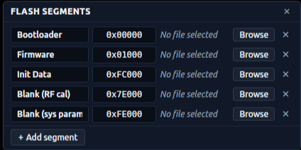
Select Files — firmware segments with addresses and file selection
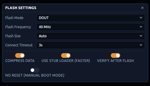
Flash Settings — mode, frequency, size, timeouts, and toggle options
Other buttons
- "Erase" — erase the entire flash memory
- "Detect" — identify the connected chip (name, flash size, MAC address)
Example: ESP8266 AT firmware (1MB flash)
Segment 1: Bootloader    @ 0x00000  → boot_v1.7.bin
Segment 2: Firmware      @ 0x01000  → user1.1024.new.2.bin
Segment 3: Init Data     @ 0xFC000  → esp_init_data_default.bin
Segment 4: Blank (RF)    @ 0x7E000  → blank.bin
Segment 5: Blank (sys) @ 0xFE000 → blank.bin Local AI — built-in llama.cpp (offline, no setup)
ComIO.Studio ships with an embedded llama.cpp runtime — you can run a local LLM model fully offline, with no API key, no terminal, no Node.js. Everything happens inside the app.
How to enable
- Open the AI panel in the right side of the app.
- Click AI Settings → Local Models.
- Pick a model from the list and click Download (GGUF format, a few hundred MB to several GB depending on the model).
- Once download finishes, select the model as the active engine and start chatting.
When to use it
- Offline / air-gapped environments — no internet required after the model is downloaded.
- Privacy-sensitive work — prompts and replies never leave your machine.
- Zero recurring cost — no subscription, no per-query billing.
Pre-tested models
These small GGUF models were verified to work with the AI assistant (reasoning shown as a collapsible block, tool calling as actions):
- Nemotron 3 Nano 4B Q8_0
- Qwen3.5 9B Q4_K_M
- GLM 4.6V-Flash Q4_K_M
- Gemma 4 E4B IT Q6_K
- Gemma 4 12B IT Q4_K_M
OpenRouter — BYOK (one API key, hundreds of models)
OpenRouter is a single API gateway that gives you access to hundreds of LLMs (Claude, GPT, Gemini, Llama, Mistral, DeepSeek and more) with one API key and one bill. No terminal, no CLI install — just paste a key into the app.
How to set it up
- Create an account at openrouter.ai and top up some credit (pay-as-you-go).
- Go to openrouter.ai/keys and generate a new API key (it looks like
sk-or-v1-…). - In ComIO.Studio, open the AI panel → AI Settings → OpenRouter.
- Paste the key, pick a model from the dropdown, and save.
When to use it
- You want to compare models easily — switch between Claude, GPT-4, Gemini, etc. from one dropdown without managing multiple API keys.
- You don't want to install a CLI agent like Claude Code or Codex.
- You need cost transparency — OpenRouter shows per-request pricing on their dashboard.
AI Agents — Claude Code & Codex (one-click)
Beyond the built-in local model and OpenRouter, ComIO.Studio can also drive an external AI agent — Claude Code (Anthropic) or Codex (OpenAI). You don't need a terminal, Node.js or any commands — the app installs it and signs you in, straight from the AI panel.
Open the AI panel (the AI button in the title bar), then the ⚙ (gear) → Settings, and pick Claude Code or Codex as the Engine. The panel then guides you with the buttons described below.
Claude Code by Anthropic
- Already on your system? ComIO.Studio detects it automatically — nothing to do.
- Not installed? The panel shows an Install button. Click it — the app downloads and installs Claude Code for you. No terminal, no Node.js, no commands.
- Sign in. After installing, the panel shows a Sign in button. Click it and log in with your Claude.ai account in the browser — billing goes through your Anthropic subscription, no API key needed.
- Then choose a model and start chatting.
Codex by OpenAI
- Already on your system? ComIO.Studio detects it automatically — nothing to do.
- Not installed? The panel shows an Install button. Click it — the app installs Codex for you. No terminal, no Node.js, no commands.
- Sign in. After installing, click the Sign in button and log in with your ChatGPT account in the browser — billing goes through your OpenAI subscription, no API key needed.
- Then choose a model from the dropdown (the list comes from your OpenAI account) and start chatting.
AI Assistant
The AI panel on the right side is a chat assistant that understands your serial communication context. It sees your port configuration, recent terminal data, and can help with protocol analysis, troubleshooting, and code generation.
🔌 Already have ChatGPT Plus or Claude Pro? Plug it in as your AI provider.
ComIO.Studio uses BYOK (Bring Your Own Key) — you sign in to an AI provider, and ComIO.Studio routes the assistant's requests through it. Most developers already have a personal AI subscription that works perfectly as that provider:
- ChatGPT Plus / Pro → install Codex CLI and sign in with your existing account
- Claude Pro / Max → install Claude Code CLI and sign in with your existing account
To set up Claude Code or Codex (one click, no terminal), jump to the AI Agents section.
Opening the AI panel
Click the AI button in the title bar to show or hide the AI panel.
Tabs
- Chat — main conversation interface
- History — saved chat sessions (↩ to load a previous session, ✕ to delete it)
- Settings — customize the AI behavior:
- Temperature — controls response creativity (lower = more precise, higher = more creative)
- AI Assistant Instruction — custom system prompt that tells the AI how to behave, what domain to focus on, etc.
Using the chat
- Type your question in the input field
- Press Enter or click "Send"
- The AI automatically sees your serial port config and recent terminal data as context
- During generation, the button changes to "Cancel" — click to stop
- Click + to start a new chat session
What you can ask
- "What protocol is this data?" — paste hex data for protocol identification
- "Why is my device not responding?" — troubleshooting with context
- "Write a Lua script that reads temperature every 5 seconds"
- "Decode this frame: 01 03 04 00 64 00 C8" — byte-level Modbus analysis
- "What baud rate should I use for this chip?"
- "Explain what my device is sending" — AI reads terminal buffer and analyzes
 Logging to File
The Logging section in the sidebar captures serial data to a downloadable file — separate from the terminal display.
How to use
- Toggle "Log" ON — logging starts immediately
- Choose format:
- Text — plain text output
- Hex — raw bytes in hexadecimal
- Mixed (default) — text with hex for non-printable bytes
- Toggle "TS" to add timestamps (
[HH:MM:SS.mmm]) to each line (ON by default) - Click "Download" to save the log as a
.txtfile - Toggle "Log" OFF when done
The log captures both RX and TX data with direction prefixes. Buffer holds up to 100,000 lines.
 Menu Bar & Panels
The title bar contains the application menu and window controls.
File menu
- New session — reset the workspace
- Exit — close the application
Edit menu
- Copy — copy selected terminal text
- Paste — paste into the command input
- Select all — select all terminal content
View menu
- Language — switch UI language
- Theme — change color scheme
- Panels — show/hide sidebar sections: Connection, Statistics, Macros, Triggers, Lua Script, Logging
ComIO menu
- License — view or enter your license key
- Pricing & Plans — subscription options
- About — application version info
Need more information?
Check out the about page or contact us directly.
What is ComIO.Studio? → View pricing plans → ✉ Contact us